
How Do Fiber Optic Cables Work?
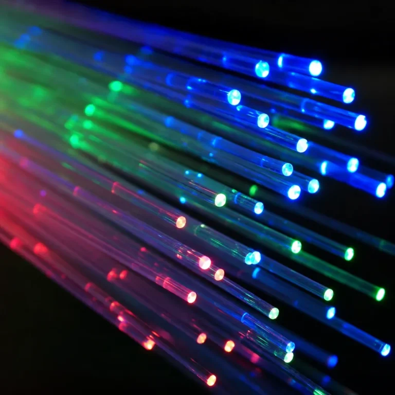
Beneath our oceans and under city streets lies a complex network of glass threads that power the global internet. But how do fiber optic cables work? At its core, this technology sends information encoded in pulses of light through glass or plastic fibers. While it sounds like science fiction, it is grounded in well-understood physics that has been refined over decades of engineering.
This guide breaks down everything you need to know: the anatomy of a fiber optic cable, how light carries data, the differences between cable types, and practical tips for installation. If you are new to fiber optics, start with our beginner’s guide to fiber optic cables before diving deeper here.
The Core Science: How Light Travels Through Glass
The foundation of fiber optic technology is a phenomenon called total internal reflection. To understand it, you first need to understand what a fiber optic cable is made of.
Anatomy of a Fiber Optic Cable
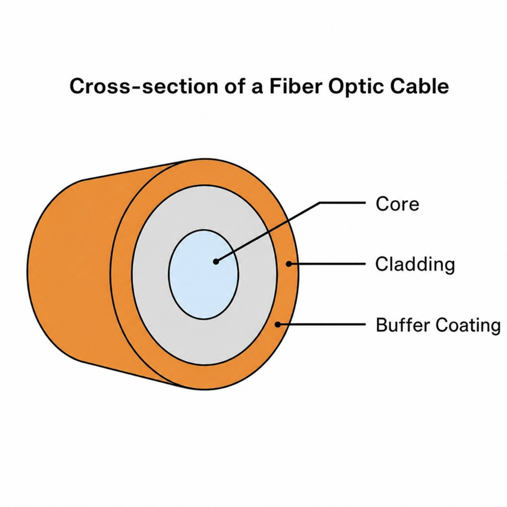
Each fiber is drawn from extremely pure silica glass heated in a specialized tower and stretched into a thread thinner than a human hair. Despite its microscopic size, every fiber has three distinct layers:
- Core: The innermost layer where light travels. Made of highly purified glass (or plastic in lower-grade cables), it has a precisely engineered refractive index.
- Cladding: A layer of glass surrounding the core with a slightly lower refractive index than the core. This difference is the key to trapping light inside.
- Buffer coating: The outermost plastic layer that protects the fragile glass from moisture, physical damage, and environmental stress.
Total Internal Reflection
When light enters the glass core, it does not travel in a perfectly straight line through the cable. As the cable bends around corners or snakes through conduit, the light constantly strikes the boundary between the core and the cladding. Because the cladding has a lower refractive index, any light hitting that boundary at a shallow angle bounces back into the core rather than passing through. This is total internal reflection.
The result is that a light pulse entering one end of the fiber travels the full length of the cable with minimal loss, regardless of how many bends the cable makes along the way. This is fundamentally different from copper cable, where electrical resistance causes the signal to weaken continuously over distance.
How Do Fiber Optic Cables Work? Translating Digital Signals into Light Pulses
Understanding that light bounces through glass is one thing. Understanding how an email, a video stream, or a voice call becomes a beam of light is another.
All digital data is ultimately a sequence of 1s and 0s. A fiber optic transceiver at the sending end converts electrical signals from your network equipment into rapid pulses of light: a flash of light represents a 1, and no light represents a 0. High-speed transceivers can flash on and off billions of times per second, enabling the enormous data rates fiber optic networks are capable of.
At the receiving end, a photodiode detects each light pulse and converts it back into an electrical signal that the connected device can read. The transceiver performs this conversion in both directions simultaneously, which is why a single fiber connection can support full-duplex communication.
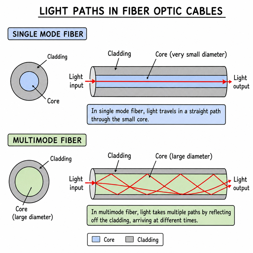
The light source used matters. Single-mode fiber uses a laser, which produces a highly focused, coherent beam suitable for very long distances. Multimode fiber typically uses a vertical-cavity surface-emitting laser (VCSEL) or LED, which is less precise but significantly cheaper for short-range applications.
Fiber Optic Cable Types: Single-Mode vs. Multimode
Not all fiber optic cables are built the same. The two primary types differ in core diameter, light source, distance capability, and cost. For a full comparison, see our dedicated article on single mode vs multimode fiber.
Single-Mode Fiber
Single-mode fiber has a very narrow core, typically 8 to 9 microns in diameter. Because the core is so small, light travels in a single straight path (a single mode) without bouncing off the cladding. This eliminates the modal dispersion that limits multimode fiber over distance. With a laser light source, single-mode fiber can carry data over 80 to 120 kilometers without amplification, making it the standard for:
- Long-haul telecommunications and internet backbone networks
- Submarine cable systems
- Inter-building campus connections
- Wide area networks (WANs)
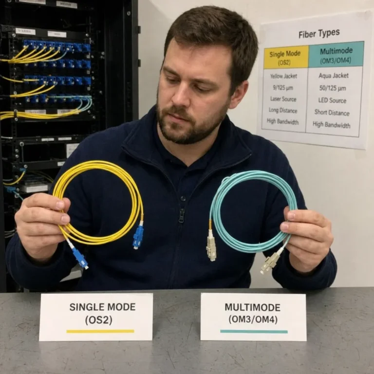
Single-mode fiber is identified by a yellow outer jacket and conforms to OS1 or OS2 standards. The transceivers and connectors it requires cost more than multimode equivalents, but prices have dropped considerably as the technology has matured.
Multimode Fiber
Multimode fiber has a larger core, either 50 or 62.5 microns in diameter, that allows multiple modes of light to travel simultaneously. Different light paths arrive at the destination at slightly different times, a phenomenon called modal dispersion. Over long distances this causes signal degradation, which limits multimode fiber to runs of 300 to 550 meters depending on the OM rating and data rate.
Within that range, multimode fiber is extremely cost-effective. VCSELs and LEDs are far cheaper than lasers, and the larger core tolerates small alignment errors during connector termination. Multimode fiber is the standard choice for:
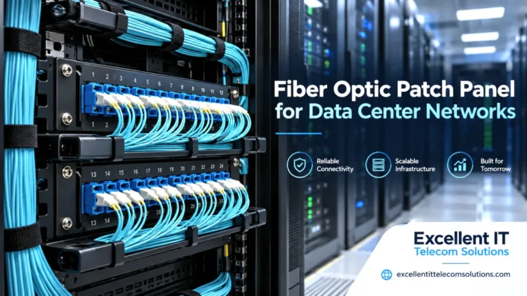
- Data center interconnects (server to switch, switch to patch panel)
- Local area networks (LANs) within a building
- Storage area networks (SANs)
- Video surveillance systems
Multimode fiber grades run from OM1 (gray jacket, older 62.5 micron core) through OM5 (lime green, optimized for wideband multimode). OM3 and OM4 (both aqua) are the current standards for new data center deployments supporting 10G, 25G, and 40G links.
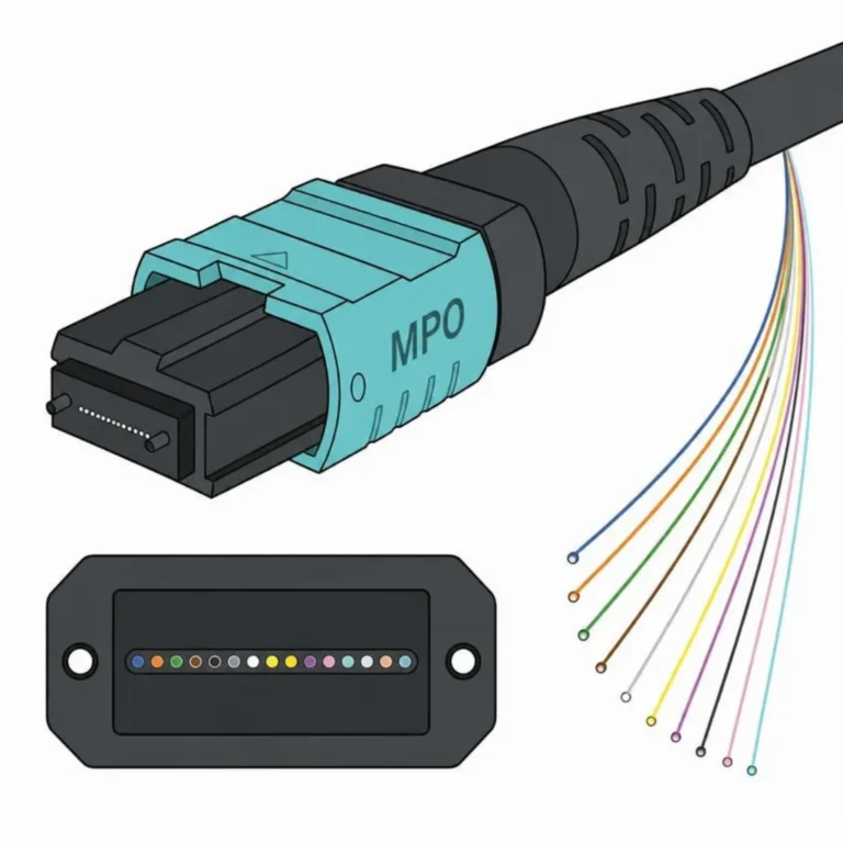
Excellent IT Telecom Solutions carries LC-LC, SC-SC, LC-SC, and MPO/MTP patch cables in both single-mode (OS2) and multimode (OM3/OM4) configurations. Whether you are connecting equipment across a data center floor or running a campus backbone, we can help you choose the right cable and length.
Why Fiber Beats Copper
For decades, copper coaxial and twisted-pair cables were the standard for telecommunications and networking. Fiber optic cables have replaced copper in virtually every high-performance application. Here is why:
Bandwidth
Copper transmits data as electrical current, and there is a hard physical ceiling on how many frequencies can be pushed through a copper conductor before they interfere with each other. Photons travel at much higher frequencies, giving fiber an effectively much larger bandwidth capacity. A single fiber strand using dense wavelength-division multiplexing (DWDM) can carry dozens of independent data streams simultaneously, each on a different wavelength of light.
Distance and Signal Loss
Electrical signals in copper lose strength due to resistance, requiring amplifiers every few hundred meters in demanding installations. Signal attenuation in fiber optics, caused by microscopic impurities in the glass, is far lower. A high-quality single-mode fiber link can run for dozens of kilometers before needing regeneration, versus 100 meters for copper Ethernet without a switch or repeater.
Electromagnetic Interference Immunity
Copper cables act as antennas, picking up electromagnetic interference (EMI) from nearby power lines, motors, radio transmitters, and lightning. Fiber optics carry light, not electricity, making them completely immune to EMI and radio frequency interference (RFI). This makes fiber the preferred choice in industrial facilities, hospitals, data centers, and anywhere electrical noise is present.
Security
Copper cable radiates a detectable electromagnetic field that can be passively intercepted with the right equipment. Tapping a fiber link requires physically disturbing the cable in a way that causes measurable signal loss, which modern monitoring systems can detect. This makes fiber significantly more secure for sensitive communications.
Real-World Applications of Fiber Optic Technology
Fiber optic networking powers a wide range of industries and use cases beyond standard internet connectivity:
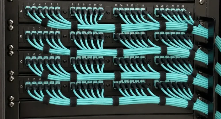
- Data centers: High-density MPO/MTP fiber assemblies connect servers, switches, and storage systems at 40G, 100G, and 400G. The short distances and high port density of data centers make OM3/OM4 multimode fiber the practical standard.
- Telecommunications: Single-mode fiber forms the backbone of every major carrier network, connecting cities, countries, and continents through terrestrial and submarine cable systems.
- Healthcare: Fiber optic bundles inside endoscopes carry light to illuminate and capture images inside the human body, enabling minimally invasive diagnostics and surgery without electrical components at the tip.
- Military and defense: The EMI immunity and difficulty of passive interception make fiber the standard for secure command and communications networks in the field and in facilities.
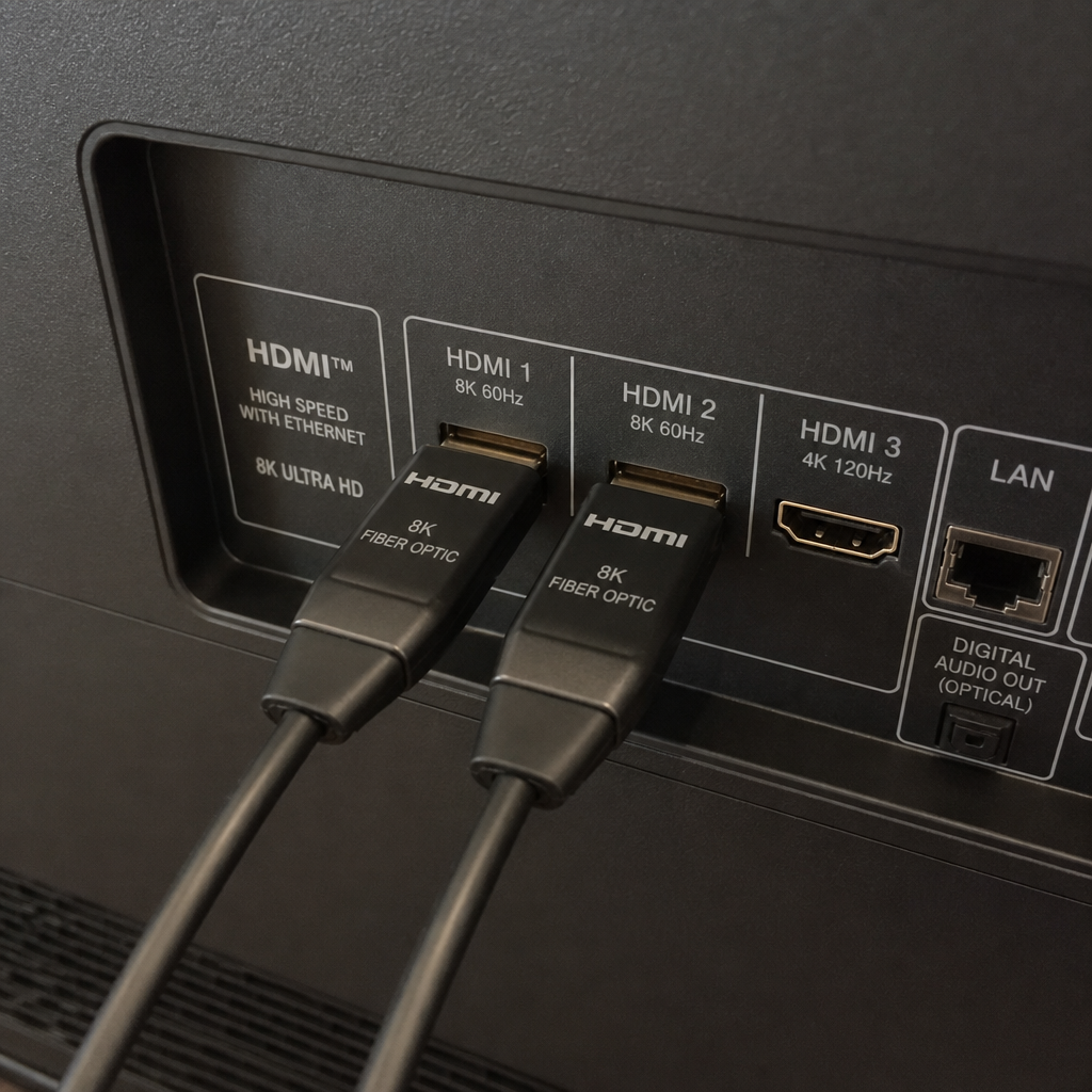
- Home theaters and AV installations: Over long HDMI cable runs, copper HDMI loses signal integrity. Fiber optic HDMI cables carry uncompressed 4K and 8K video with audio over 30 meters or more with zero degradation, making them the right choice for large custom installations.
Fiber Cable Installation: Key Practices
Installing fiber optic cable requires more care than copper. The glass fibers inside are strong under tension along their length but will crack or shatter if bent too sharply. Every cable carries a minimum bend radius specification that must be observed throughout installation.
Minimum Bend Radius
If a fiber cable is bent tighter than its specified minimum bend radius, the glass core can micro-fracture or the angle of total internal reflection can be disrupted, causing light to leak into the cladding and the signal to fail. Always route fiber with gentle curves, use appropriate bend radius limiters at cable management points, and never force a cable around a tight corner.
Fusion Splicing
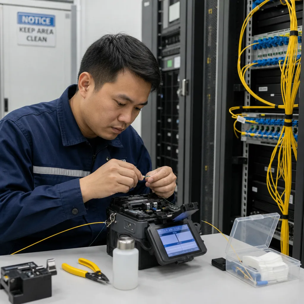
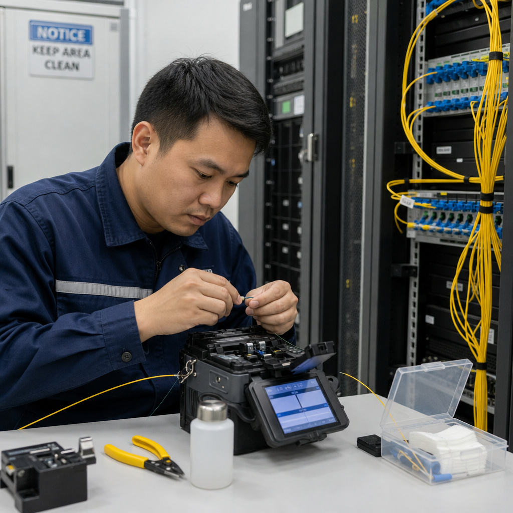
When two fiber cables need to be joined mid-run, the connection is made with a fusion splicer. This precision instrument aligns the microscopic glass cores of the two fibers and uses an electric arc to melt them together. A proper fusion splice introduces less than 0.1 dB of signal loss. Cleanliness is essential: even a single dust particle on the fiber end face can cause the splice to fail. Work in a clean environment and use lint-free wipes.
Connector Cleanliness
Dirty fiber connectors are the leading cause of signal loss and link failures in fiber optic networks. A fingerprint, dust particle, or oil film on the end face of an LC or SC connector can block enough light to take down a link. Always inspect connectors with a fiber microscope before mating, and clean with a fiber optic cleaning pen or lint-free wipe moistened with isopropyl alcohol. Never connect a fiber cable without inspecting and cleaning the connector first.
Testing After Installation
Every fiber link should be tested after installation using an optical power meter or an OTDR (optical time-domain reflectometer). An OTDR can identify the location and magnitude of every splice, connector, and bend in the link, confirming performance meets specification before equipment is connected.
Conclusion
Fiber optic cables work by converting digital data into pulses of light that travel through a glass core using total internal reflection. Because light experiences far less signal loss than electrical current in copper, and because it is immune to electromagnetic interference, fiber can carry vastly more data over much longer distances than any copper alternative. The choice between single-mode and multimode fiber comes down to distance and budget: single-mode for long hauls, multimode for within-building and data center applications.
Understanding how fiber optic cables work gives you the foundation to make better decisions when specifying, installing, and troubleshooting fiber networks.
Excellent IT Telecom Solutions in Irving, Texas supplies fiber patch cables, MPO/MTP trunk assemblies, and fiber accessories for data centers, enterprise networks, and telecommunications projects. Our team can help you specify the right cable type, connector, and length for your application.