
What Is an MPO Connector and How Is It Used in Data Centers?
MPO connectors are the standard interface for high-density fiber cabling in modern data centers. A single MPO connector can terminate 8, 12, or 24 fibers in the space that one LC or SC connector occupies, making it the practical choice for any environment where port density and cable management matter. Understanding what an MPO connector is, how it is built, and how it maps to the transceivers and speeds running in your data center is essential before ordering any fiber cabling.
What Is an MPO Connector?
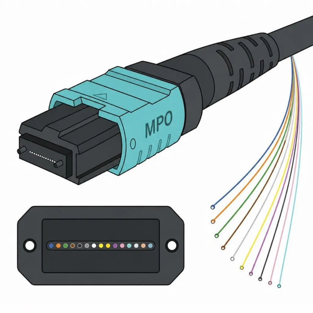
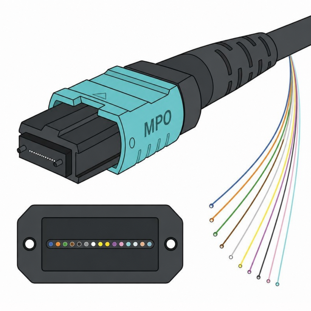
MPO stands for Multi-fiber Push-On. It is a fiber optic connector standard defined by IEC 61754-7 and TIA-604-5 that houses multiple fibers in a single rectangular MT (Mechanical Transfer) ferrule. The push-on latching mechanism allows the connector to be mated and released quickly without tools, which is why MPO connectors are the default choice for pre-terminated trunk cable systems in data centers.
The key advantage over individual LC or SC connectors is density. Where a 24-fiber LC duplex panel requires 12 individual LC adapters, a single 24-fiber MPO adapter replaces all of them in a fraction of the space. This density benefit is magnified in large data centers where hundreds or thousands of connections must be managed in limited rack units.
MPO connectors are the foundation of the parallel optics model used by 40G, 100G, 200G, and 400G transceivers. Instead of sending all data on a single wavelength at very high speed, parallel optics splits traffic across multiple fiber lanes running simultaneously. The MPO connector is what makes this multi-lane transmission physically possible in a compact, field-deployable format.
Internal Structure of an MPO Connector
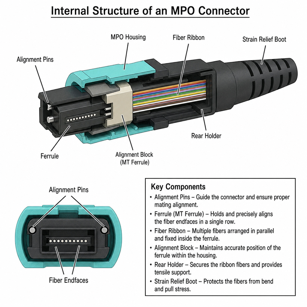
An MPO connector has more internal components than a standard single-fiber connector. Each part plays a specific role in achieving accurate fiber alignment at mating:
- MT Ferrule: The rectangular polymer ferrule that holds all fibers in a single row (or two rows in 24-fiber designs). Fiber positions are precisely spaced 250 micrometers apart. The ferrule is the most critical component for optical performance — tighter ferrule tolerances produce lower insertion loss.
- Alignment Pins: Two steel guide pins (on male connectors) that insert into guide holes on the mating female connector to precisely align the fiber arrays. Misalignment of even a few micrometers causes measurable signal loss.
- Fiber Ribbon: The individual fibers are arranged in a flat ribbon inside the connector body, color-coded for identification (see color coding section below).
- Alignment Block: Maintains the ferrule position within the housing, ensuring consistent spring force and mating angle.
- Rear Holder: Anchors the fiber ribbon and provides tensile strength relief at the entry point of the connector body.
- Strain Relief Boot: The flexible boot at the cable entry protects the fibers from bending stress and pull forces during handling.
MPO Connector Types: 8-Fiber, 12-Fiber, and 24-Fiber
The fiber count of an MPO connector determines which transceivers and network speeds it supports. Choosing the wrong count means the cable physically cannot serve the intended equipment.
8-Fiber MPO
The 8-fiber MPO is used primarily with 40G QSFP+ transceivers using the SR4 protocol. 40G SR4 splits the 40G signal across four transmit lanes and four receive lanes, using all 8 fibers. The 8-fiber MPO is also used with some 100G PSM4 (parallel single-mode) transceivers that use 4 transmit and 4 receive lanes on OS2 single-mode fiber.
12-Fiber MPO
The 12-fiber MPO is the most widely deployed configuration in data centers. It supports:
- 100G QSFP28 SR4: Uses 4 transmit and 4 receive lanes (8 of the 12 fibers active; 4 unused)
- 100G QSFP28 PSM4: Uses all 8 active fibers on single-mode OS2
- 40G QSFP+ SR4: Uses 8 of the 12 fibers
- 200G QSFP56 SR4: Uses 8 fibers at higher lane speeds
The 12-fiber format is also the standard for MPO trunk cables and cassette-based patching systems, making it the most common assembly in structured data center cabling.
24-Fiber MPO
The 24-fiber MPO supports the highest-density applications:
- 400G QSFP-DD SR8: Uses 16 fibers (8 transmit, 8 receive) — a 24-fiber MPO provides headroom for this
- High-density trunk cables: A single 24-fiber MPO replaces two 12-fiber MPO connectors, reducing adapter count and improving cable management at patch panels
24-fiber MPO connectors use a double-row MT ferrule with two rows of 12 fibers, which requires compatible adapters — standard 12-fiber MPO adapters will not accept a 24-fiber plug.
Excellent IT Telecom Solutions supplies 8-fiber, 12-fiber, and 24-fiber MPO/MTP trunk cables, breakout harnesses, and patch cables in OM3, OM4, and OS2 configurations. We serve data centers and enterprise networks from our Irving, Texas location.
MPO Connector Color Coding
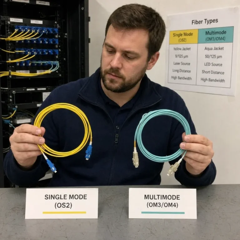
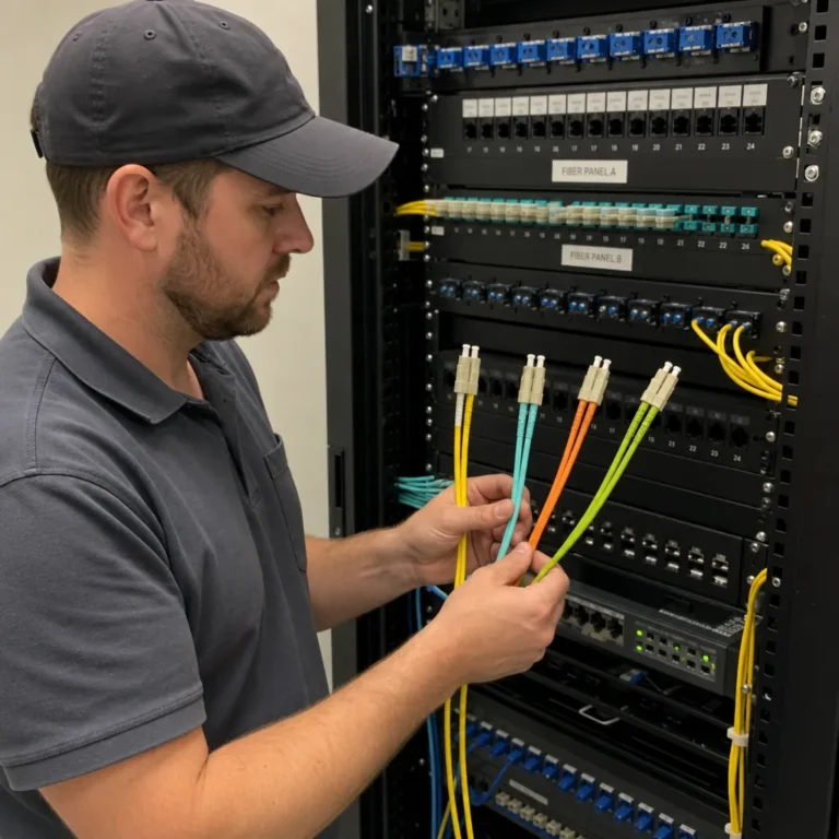
The outer housing color of an MPO connector indicates the fiber type inside. This allows technicians to identify the correct cable at a glance without reading labels, which matters when managing dozens of cables in a dense patch panel.
| Housing Color | Fiber Type | Common Applications |
|---|---|---|
| Aqua | OM3 multimode | 10G/40G/100G within building, up to 300m |
| Aqua or Violet/Erika | OM4 multimode | 10G/40G/100G within building, up to 400-550m |
| Lime Green | OM5 multimode | Wideband multimode, short wavelength division multiplexing |
| Yellow | OS2 single-mode | Long-distance links, PSM4, inter-building |
Note: OM3 and OM4 both use aqua connectors in most products. Some manufacturers distinguish OM4 with a violet or erika (light purple) housing. Always verify the fiber type from the cable label or test documentation rather than relying on color alone when mixing assemblies from different suppliers.
Inside the cable, the individual fibers within the ribbon follow the TIA-598 color code standard: blue, orange, green, brown, slate, white, red, black, yellow, violet, rose, and aqua for positions 1 through 12. This standard order defines the transmit and receive lane assignments for each transceiver type and is the basis for polarity planning.
Male vs. Female: Guide Pins and Connector Gender
Every MPO connector is either male (pinned) or female (unpinned). A male connector has two steel guide pins protruding from the ferrule face. A female connector has guide holes that accept those pins. A mated pair must always be one male and one female; two male connectors cannot be mated without special pin-removal tooling, and attempting to do so damages both connectors.
In a typical data center structured cabling system:
- MPO trunk cables between patch panels are usually female-to-female
- The cassette or adapter modules at the patch panel interface provide the polarity conversion and the male connector where needed
- Transceiver ports accept female MPO connectors in most designs
Always confirm the gender at each end of the cable before ordering, and verify that the adapter plates or cassettes in your patch system are compatible.
MPO Polarity in Data Centers
Polarity is the requirement that transmit fibers at one end of a link connect to receive fibers at the other end. With individual LC or SC connectors this is managed by swapping the two fibers of a duplex pair. With MPO connectors managing 8 or 12 fibers simultaneously, polarity must be planned at the system level before any cabling is ordered.
TIA-568 defines three polarity methods for MPO-based systems:
- Method A (Straight): Trunk cables are straight-through (fiber 1 at one end connects to fiber 1 at the other). Polarity is resolved at the equipment end using cross-over patch cords or cassettes. Most cassette-based patching systems use Method A trunks.
- Method B (Crossover): The trunk cable reverses fiber positions end-to-end (fiber 1 at one end connects to fiber 12 at the other). Patch cords at both ends are straight-through. Less common in modern systems.
- Method C (Pair-reversed): Each adjacent fiber pair within the trunk is swapped. Rarely used in new designs.
Mixing polarity methods across different segments of the same channel is the most common cause of fiber links that are physically connected but non-functional. Standardize on one method across the project and document it before ordering assemblies.
MPO in Data Center Cabling Architecture
MPO connectors are used at every tier of the data center fiber cabling hierarchy:
Trunk Cables
MPO trunk cables run between patch panels at the top-of-rack (ToR) layer and the aggregation layer, or between MDA (Main Distribution Area) and HDA (Horizontal Distribution Area) in structured cabling designs. A single 12-fiber MPO trunk replaces 6 LC duplex jumpers in the same pathway. Trunks are typically pre-tested factory assemblies that are faster to deploy and more reliable than field-terminated cable.
Breakout Harnesses (Hydra Cables)
A breakout harness, sometimes called a hydra cable, has an MPO connector on one end that fans out to individual LC or SC connectors on the other. This allows a single MPO port on a switch or patch panel to connect to 4 or 6 individual equipment ports. Breakout harnesses are commonly used to connect ToR switches directly to servers without going through a cassette-based patch system.
EITS carries MPO breakout cables in standard configurations for common switch and server port layouts.
Cassette-Based Patching Systems
A cassette (also called a module or adapter module) converts an MPO trunk port into individual LC or SC adapter ports on the front face of a patch panel. Cassettes are the most flexible approach for data centers that reconfigure frequently because individual LC patch cords can be moved at the front of the panel without touching the trunk cables behind it.
Performance and Installation Best Practices
MPO connectors have 8, 12, or 24 fiber end faces in a single ferrule. Contamination affects all fibers simultaneously, which means a single dirty MPO connector can take down multiple 10G or 25G lanes at once. The consequences are more severe than with single-fiber connectors.
- Inspect before every mating: Use an MPO-compatible fiber inspection scope (standard LC/SC scopes cannot reach the recessed MPO ferrule). Inspect every fiber position in the ferrule, not just a spot check.
- Use MPO-specific cleaning tools: Standard LC cleaning pens do not fit MPO ferrules. Use MPO cleaning sticks or cassette-style MPO cleaners designed for the connector format.
- Test every fiber: Verify insertion loss for every fiber in every connector after installation using a calibrated MPO test source and power meter. Factory test reports cover the cable at the time of manufacture; field conditions can degrade performance.
- Respect the minimum bend radius: MPO trunk cables typically have a larger minimum bend radius than individual fiber jumpers due to the ribbon fiber construction inside. Check the manufacturer’s specification and use appropriately sized cable management.
- Store with dust caps: Keep MPO connectors capped whenever they are not mated. Ferrule contamination accumulates quickly in dusty environments.
MPO vs. MTP: A Brief Note
MTP is a registered trademark of US Conec for a premium MPO-style connector engineered to tighter tolerances, with a removable/reversible housing and improved mechanical consistency. Every MTP connector is an MPO, but not every MPO connector is an MTP. For a full comparison, see our dedicated article on MTP vs MPO connectors.
Conclusion
MPO connectors are the practical foundation of high-density fiber cabling in data centers. Choosing the right fiber count for your transceiver type, getting polarity right before ordering, confirming male/female gender at each interface, and maintaining connectors properly are the four decisions that determine whether an MPO-based cabling system performs reliably or becomes a source of persistent link failures.
Excellent IT Telecom Solutions supplies MPO trunk cables, breakout harnesses, and cassette systems for data center and enterprise fiber networks. Our team can help you specify fiber count, polarity, gender, and jacket type for your specific cabling design.