
MPO Breakout Cable Explained: How 40G and 100G Networks Use It
As data centers scale to meet growing bandwidth demands, the transition from 10G to 40G and 100G architectures creates a cabling challenge: switch ports now carry multiple 10G or 25G lanes bundled into a single high-density MPO interface, while servers and storage devices still connect over individual LC duplex ports. The MPO breakout cable is what bridges these two worlds, splitting one multi-fiber connection into several individual fiber pairs without requiring a patch panel or cassette in between.
What Is an MPO Breakout Cable?
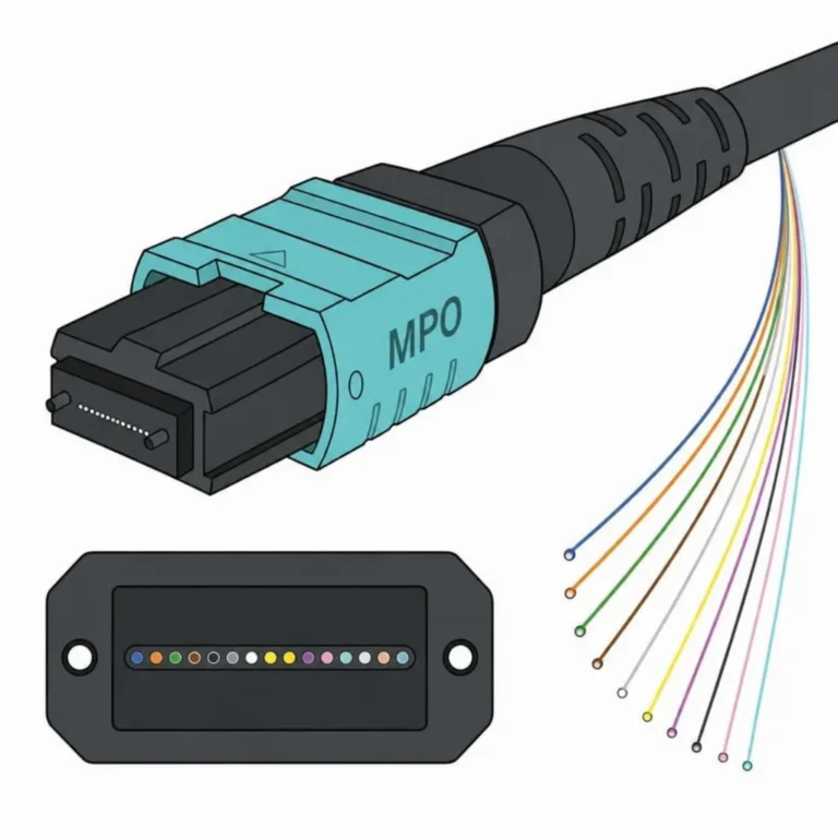
An MPO breakout cable, also called a fanout cable or hydra cable, has an MPO connector on one end and multiple individual duplex fiber connectors on the other. The most common configuration is MPO to LC, where one 12-fiber MPO connector fans out into six LC duplex legs, each carrying one transmit and one receive fiber. MPO to SC breakout cables also exist for connecting to older equipment that uses SC ports.
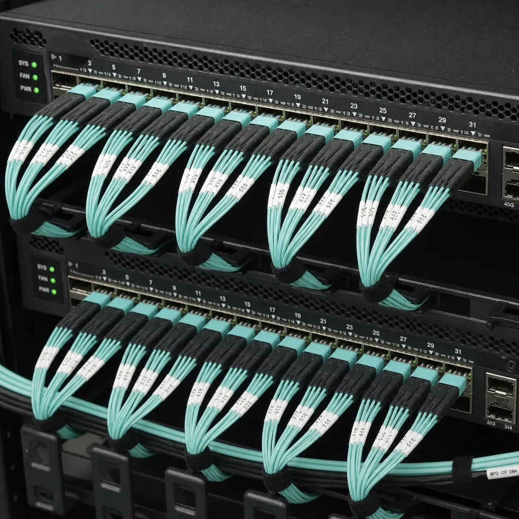
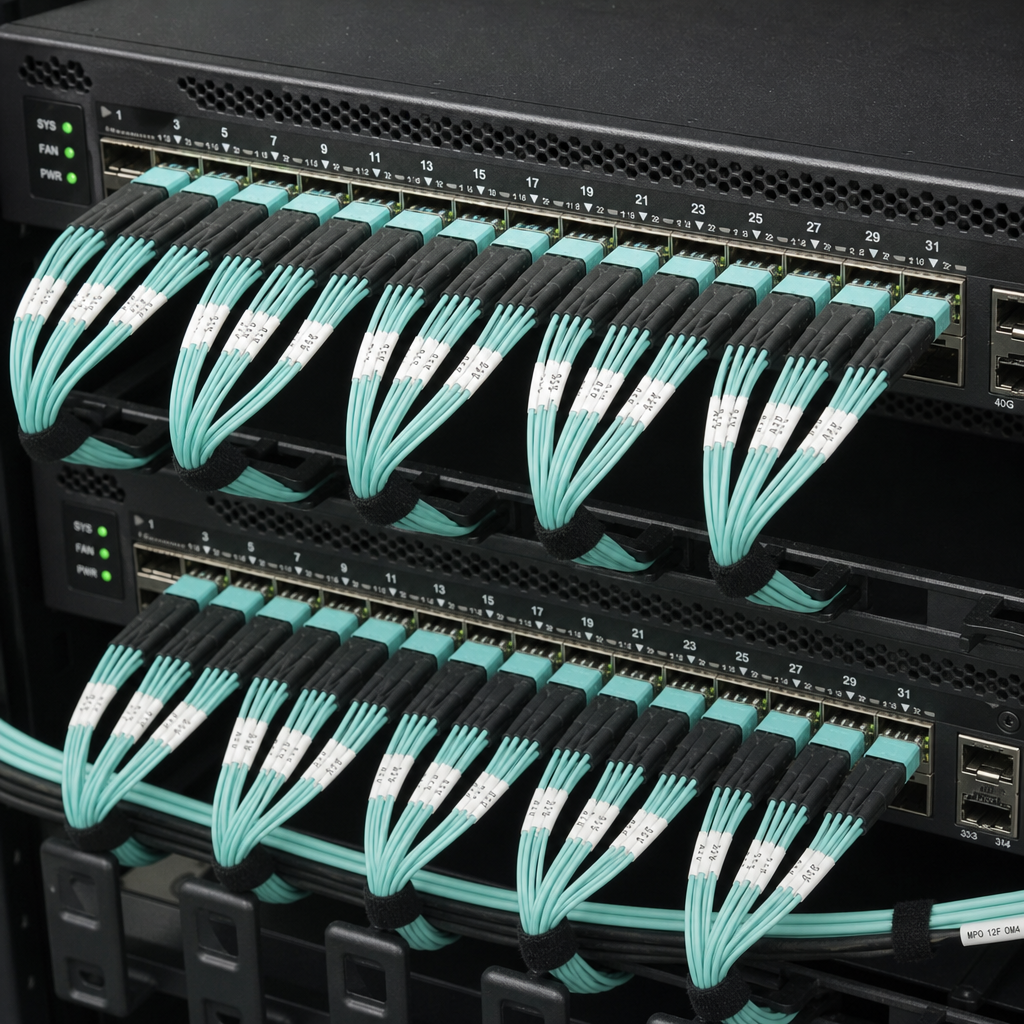
The breakout cable eliminates a layer of infrastructure. Instead of running an MPO trunk cable to a patch panel cassette and then patching individual LC cords to equipment, a breakout cable connects the switch port directly to server or storage ports in a single cable assembly. This reduces connection points, lowers insertion loss, and simplifies cable management in top-of-rack deployments.
Why 40G and 100G Require Parallel Optics
To understand why breakout cables exist, you need to understand how 40G and 100G transceivers actually transmit data.
Earlier 1G and 10G networks used duplex fiber: one fiber to transmit, one to receive, carrying a single high-speed optical lane in each direction. Pushing 40G or 100G over a single fiber pair requires extremely high-frequency lasers and is costly and distance-limited. Parallel optics solves this by splitting the total bandwidth across multiple lower-speed lanes running simultaneously, each on a separate fiber.
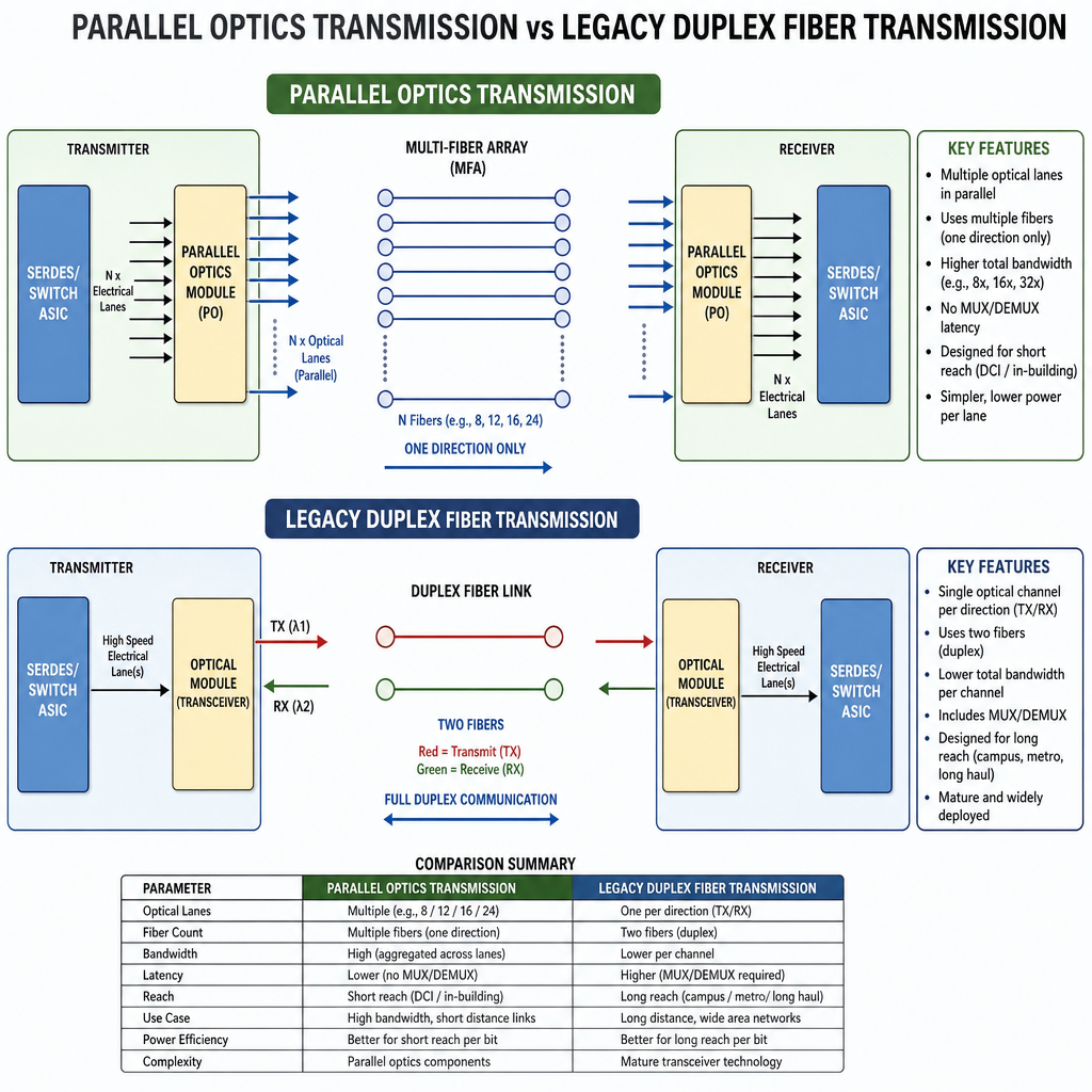
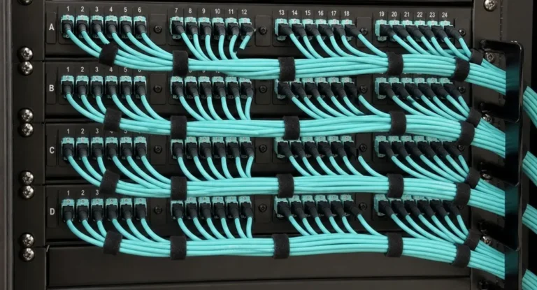
Because MPO connectors house 8, 12, or 24 fibers in a single compact interface, they are the standard connector for parallel optic transceivers. The MPO breakout cable takes those parallel lanes and separates them into individual duplex connections that standard SFP+ or SFP28 ports can use.
40G Breakout: QSFP+ to 4x10G SFP+
A 40G QSFP+ transceiver using the SR4 protocol transmits on four independent 10G lanes and receives on four independent 10G lanes, using 8 fibers total. When you plug an MPO to LC breakout cable into a 40G QSFP+ port, the four transmit fibers on the MPO end separate into four individual LC duplex legs, each carrying one 10G lane. Each LC leg connects to a standard 10G SFP+ port on a server or access switch.
The result: one 40G switch port connects to four separate 10G devices over a single breakout cable. This is one of the most common cabling patterns in data centers with a mix of 40G core or aggregation switches and 10G servers.
Lane mapping for 40G SR4 on a 12-fiber MPO breakout:
- Fibers 1-4: Transmit lanes (Tx1, Tx2, Tx3, Tx4)
- Fibers 7-10: Receive lanes (Rx1, Rx2, Rx3, Rx4)
- Fibers 5, 6, 11, 12: Unused (dark)
100G Breakout: QSFP28 to 4x25G SFP28
A 100G QSFP28 SR4 transceiver follows the same parallel optics principle, but each lane runs at 25G instead of 10G. Four transmit lanes plus four receive lanes again totals 8 active fibers on a 12-fiber MPO connector. An MPO to LC breakout cable splits this into four 25G LC duplex legs, each connecting to a 25G SFP28 port.
The 100G to 4x25G breakout is the current standard pattern for connecting 100G spine or leaf switches to 25G servers. A 32-port 100G switch can serve up to 128 individual 25G server ports using breakout cables, with no additional patch infrastructure required.
Base-8 vs Base-12: Choosing the Right Architecture
Both 40G SR4 and 100G SR4 transceivers use 8 active fibers. The standard MPO connector, however, holds 12 fibers. In a 12-fiber breakout cable, 4 fibers remain unused on every connection. At scale, across hundreds of switch ports, this adds up to a significant amount of wasted fiber capacity.
Base-8 architecture addresses this by using 8-fiber MPO connectors throughout the cabling system. Every fiber in every connector is active, and cable assemblies, patch panels, and trunk cables are all designed around multiples of 8 rather than 12. This produces 100% fiber utilization with 40G and 100G SR4 transceivers.
The trade-off is standardization: most existing data center cabling infrastructure is Base-12, and a Base-8 system requires compatible Base-8 trunk cables, cassettes, and patch panels. For new deployments designed entirely around 40G and 100G parallel optics, Base-8 is the more efficient choice. For environments mixing legacy 10G duplex fiber with new 40G/100G parallel optics, Base-12 is simpler to manage.
Excellent IT Telecom Solutions supplies MPO to LC and MPO to SC breakout cables in OM3, OM4, and OS2 configurations, available in 8-fiber and 12-fiber MPO formats. We serve data centers and enterprise networks from Irving, Texas.
Fiber Type and Distance
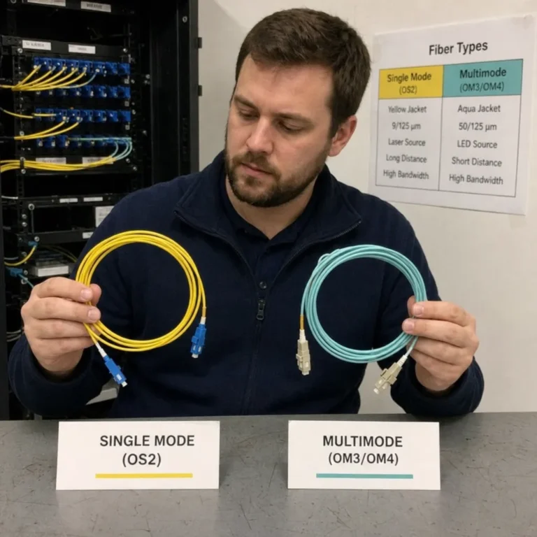
MPO breakout cables for 40G and 100G short-reach applications use multimode fiber, almost always OM4 (aqua jacket) for new installations. OM4 supports 40G SR4 up to 150 meters and 100G SR4 up to 100 meters, which covers virtually all intra-rack and inter-rack distances in a data center. OM3 is acceptable for shorter runs but is now generally considered legacy for new 100G deployments.
For longer inter-building or campus runs where multimode distance limits are exceeded, single-mode OS2 MPO breakout cables are used with PSM4 transceivers (100G QSFP28 PSM4 can reach up to 500 meters on OS2 fiber). The MPO connector format is identical; only the fiber type and transceiver change.
Breakout Cable vs Cassette: When to Use Each
The alternative to a breakout cable is a cassette-based patching system, where an MPO trunk cable runs to a patch panel and a cassette module converts the MPO port into individual LC adapter ports at the front of the panel. Individual LC patch cords then connect to equipment.
| Factor | MPO Breakout Cable | Cassette System |
|---|---|---|
| Connection points | Fewer (lower loss) | More (additional connector pair at cassette) |
| Reconfiguration | Requires replacing the whole cable | Move individual LC patch cords at the panel |
| Best for | Stable, direct server-to-switch links | Environments with frequent port moves |
| Cost | Lower (no cassette hardware) | Higher upfront (cassette modules) |
| Cable management | Fanout legs must be managed at both ends | Cleaner at the patch panel |
Breakout cables work best in top-of-rack deployments where a switch directly connects to servers in the same or adjacent rack and reconfiguration is infrequent. Cassette systems are better suited for end-of-row or middle-of-row architectures where the patch panel is a central distribution point serving many racks.
Best Practices for MPO Breakout Deployments
Use Factory-Terminated Assemblies
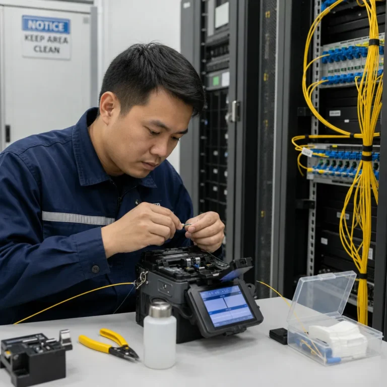
Field termination of multi-fiber MPO connectors requires specialized equipment and controlled conditions. Factory-terminated breakout cables are tested for insertion loss on every fiber before shipment. Pre-terminated assemblies are faster to deploy, more reliable, and eliminate the risk of field termination errors that can be difficult to diagnose after installation.
Verify Polarity Before Ordering
Polarity defines which fiber at the MPO end connects to which LC leg, and which LC leg carries transmit versus receive. The wrong polarity produces a link that is physically connected but non-functional. Confirm the polarity type (Method A, B, or C) matches your switch and transceiver requirements before ordering. Most 40G and 100G SR4 breakout applications use Method A polarity with Type A (straight) MPO connectors.
Plan Breakout Leg Length Carefully
The individual LC legs of a breakout cable must be long enough to reach their target ports without excess slack, but not so short that the cable is under tension. Measure the distance from the switch port to each server port before specifying leg length. Custom breakout lengths are available from most suppliers and are worth ordering for clean installations.
Inspect and Clean the MPO End
A dirty MPO connector affects all active fibers simultaneously. Use an MPO-specific cleaning tool before every mating, inspect with a fiber scope before insertion, and keep dust caps on whenever the connector is not mated. Contamination is the leading cause of unexplained lane failures in parallel optics deployments.
MTP vs MPO in Breakout Cables
Some breakout cables use MTP connectors at the MPO end rather than standard MPO connectors. MTP is a US Conec trademarked connector built to tighter tolerances than the base MPO standard, which reduces insertion loss and improves connection consistency over repeated matings. For 40G and 100G applications where the optical power budget is tight, MTP-terminated breakout cables are recommended. For a full comparison, see our article on MTP vs MPO connectors.
Conclusion
The MPO breakout cable solves the core physical challenge of parallel optics networking: getting the multiple fiber lanes packed into a single switch port transceiver connected to individual server and storage ports. Whether you are running 40G QSFP+ to four 10G SFP+ servers or splitting 100G QSFP28 across four 25G SFP28 ports, the breakout cable is the most direct and cost-effective way to make those connections in a top-of-rack deployment. Choosing the right fiber type, fiber count, polarity, and leg length before ordering ensures the assembly works correctly from day one.
Excellent IT Telecom Solutions in Irving, Texas supplies MPO to LC and MPO to SC breakout cables, MPO trunk cables, and cassette systems for 40G and 100G data center deployments. Our team can help you specify the right configuration for your switch and server ports.